IRT KilnMonitor® is a full featured computer system that allows you to monitor, process and trace data from rotary cement and steel kilns. Unlike existing solutions it is based on standard microbolometer radiometric infrared cameras, as used in a variety of different applications. IRT KilnMonitor can integrate several cameras per kiln as well as allowing several kilns to be observed at once.
2D and 3D Kiln View
Line Scan & Image from Thermal Imager
Client‐Server based
Easy set up and measure accurately and quickly kiln parameters
Kiln number monitored on one computer is only limited by the hardware performance.
Several scanners per kiln
Combinations of several scanners and pyrometers.
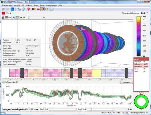
Kiln envelope profile
Permissible envelope profile with the possibility to define individual limits for different kiln zones. (Green);
Actual envelope profile. (Gray; parts outside permissible range – Red);
Alarm zones;
Last scanned line;
Envelope profile is leveled with the 2D image and is with a cursor to easily see image to profile correspondence.
Kiln shell infrared image
Temperature measurement at any kiln shell surface spot. Updated after every full rotation.
2D infrared image display
Selectable color palette;
Selectable temperature range: preset, auto or custom;
Rulers in the real kiln coordinates;
Flying spot reader: temperature at the spot, position of the spot, brick thickness, coating thickness;
Maximum kiln shell temperature is displayed;
Areas zoom in a separate window, unlimited number or zoomed areas.
Kiln design display
Kiln parts with different colors and information on every part. Brick refractory zones. Shadow zones.
Bricks and coating thickness calculation
Bricks and coating thickness is estimated using the actual kiln shell temperatures and the kiln development history stored in the database.
Specifications
Trend
Trending for spots, lines or areas of the kiln shell (spot temperature value, line and area minimum, maximum and average temperature). For the real-time data and for the historical data.
History reference
Possibility to recall any kiln state from the history and display it on the screen for reference: as kiln shell image, as envelope profile or as a difference map between the current and the history image.
Image trend
History forms one image where every line represent one record in the history.
Worst case image
Image that shows maximum temperature at every kiln shell spot over some selectable period of time.
Alarms
On-screen display, beeper, external hardware alarms and OPC alarms;
Alarms on exceeding reference envelope profile limits – upper and lower bounds;
Alarm zones: upper bound, lower bound, range. Zone number is not limited;
False alarm threshold.
Ring diagram
Brick and coating thickness of the complete kiln. Brick and coating thickness at kiln section. Brick and coating thickness at kiln interval. Colorized: greed-yellow-red.
Analysis objects on the 2D image
All analysis objects are with labels containing selectable information.
Spots: temperature, position, brick thickness, coating thickness, averaging. Unlimited number of spot objects.
Slices (kiln sections): min, max, average temperature, brick thickness, coating thickness, averaging. Unlimited number of slice objects.
Intervals: min, max, average temperature, brick thickness, coating thickness, averaging. Unlimited number of interval objects.
Lines: min, max, average temperature, averaging. Unlimited number of line objects.
Areas: min, max, average temperature, averaging. Unlimited number of area objects.
3D kiln display
Kiln “pipe” with infrared image on the surface. Kiln is rotating with the real speed.
Rings and other shadow zones.
Position of the top-kiln.
Real coordinates ruler with the kiln refractory and shadow zones structure.
Brick refractory with calculated thickness.
Coating with calculated thickness.
Possibility to view from different angles and look inside the kiln.
Section view with detailed kiln information at the section. End view.
Split by refractory zones view (also works in section and end views).
Colorized refractory zones.
Windows arrangement
All combinations of 2D and 3D windows.
Possibility to save the current arrangement as the standard and quickly recall it later.
History
Kiln state (scanned infrared image, bricks and coating thickness, alarm state) is continuously recorded in a database.
Three types of history: short-term with recording every 5 minutes, middle-term with recording every 1 hour and long-term with user-defined intervals of recording.
Possibility to load any saved kiln state by date/time and to see and analyze it with all available views (2D and 3D). Player controls: first, last, next, previous (2D and 3D). Fast playback with selectable speed (only 2D).
Client-server model
Server is the computer collecting data from the scanners. Client is any computer in the local network (or as an option – in the Internet).
Kiln information can be visualized in the same way (in 2D and 3D) on the server and on any client computer in the network.
Client-server model is implemented using OPC.
OPC
OPC Alarms and Events protocol. Alarms are published for any OPC client.
OPC Data Access protocol. Current kiln state is published for any OPC client: infrared image, kiln temperature min and max, bricks thickness minimum, coating thickness maximum, envelope profile and other information.